


IMUs
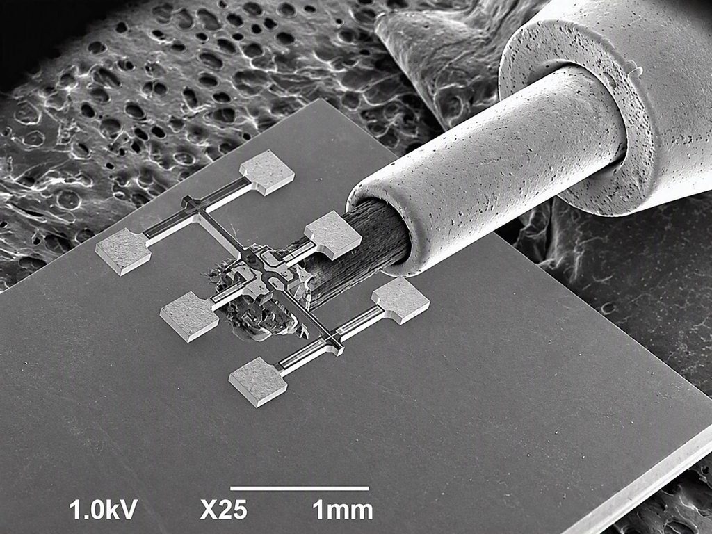
MEMS sensors like this one, to larger FOGs, RLGs and HRGs
(Image: Epson Europe Electronics)
Sensing attitude
Rory Jackson looks into the finer points of choosing the right IMU for the right platform and its mission
In a world increasingly defined by data, the precision of satellite and spacecraft operations is everything, and between the sparse updates of data from star trackers and sun sensors for attitude sensing, not to mention GNSS for position tracking, inertial measurement units (IMUs) serve as an essential aid and ingredient towards that precision.
For the unfamiliar: IMUs are composed predominantly of accelerometers for measuring linear acceleration and gyroscopes for measuring angular rate. When these are arranged in three axes, changes in position and attitude can be tracked and logged closely, to the benefit and quality of many applications.
Platforms performing Earth observation (EO) and imaging tasks, for instance, must filter for jitter (such as from flexing of their solar arrays or vibration from their camera gimbals and reaction wheels) as they capture imagery, pointing as accurately as possible to view as the mission demands, and geolocate their image data to a degree that provides actionable insights and value to customers of that data. Similarly, radar altimetry missions must be highly stabilised in their orbit and attitude for accurate measurements of land and sea height. Meanwhile, communications missions, whether LEO, GEO or MEO, must ensure extremely fine narrow-beam steering and hand-off amid jitter and absolute sensor outages.
And while inertial sensors invariably suffer some drift in their data accuracy over time – to different degrees depending on IMU type – the latency and periodic blindness of sun and star trackers make the IMU wholly indispensable for most any spacecraft’s success. Henceforth, we will investigate some of the variety of IMU products available today, and unpack some of the underlying technical principles and nuances for an understanding of their places in space engineering.
IMU ecosystem
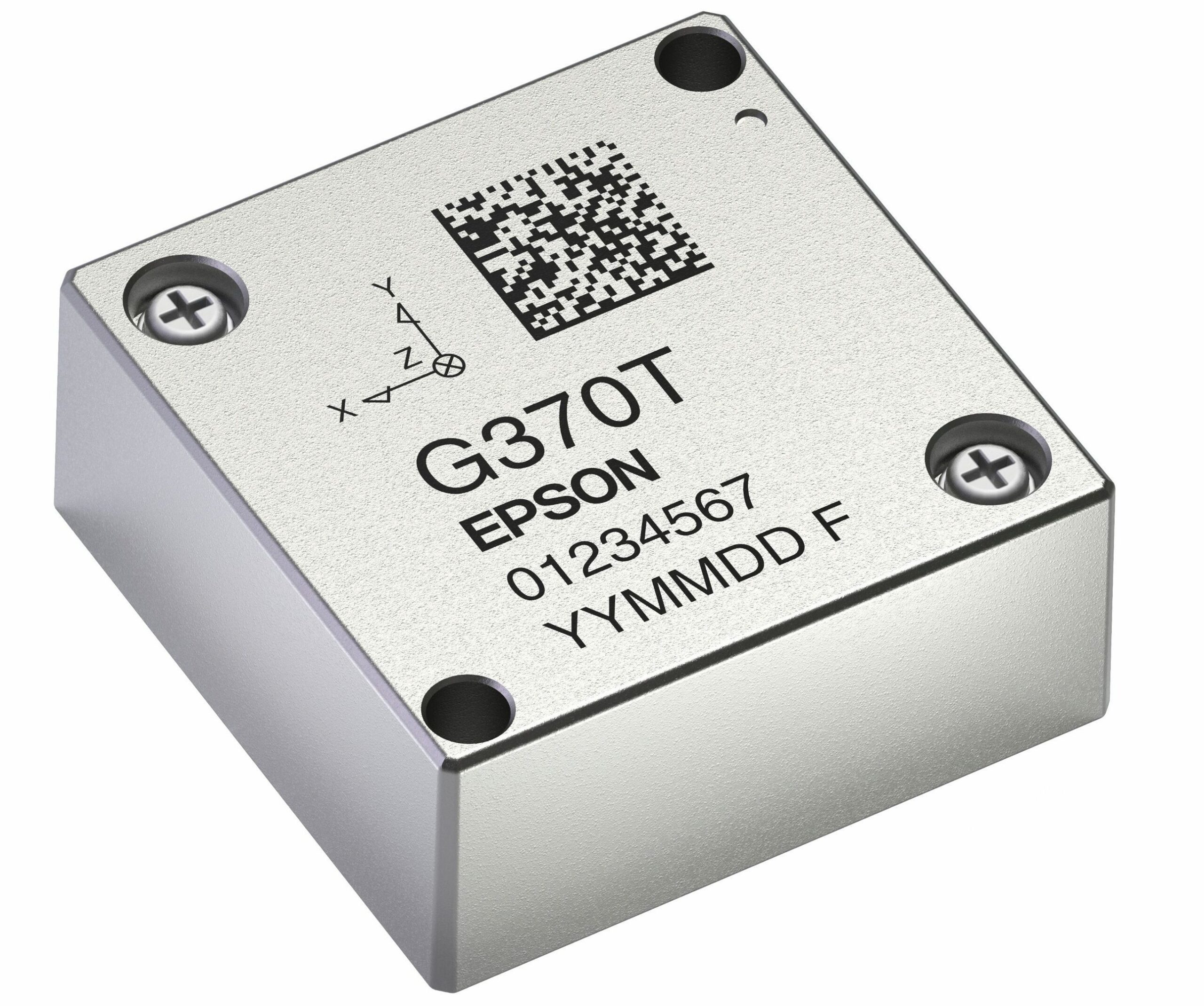
It is important to note that, in many cases, IMU suppliers to satellites and spacecraft companies do not always design their products for operations in space from the ground up. In fact, it is often the case that commercial, off-the-shelf (COTS) IMUs manufactured as general industry products are appealing for integration into space applications purely by virtue of their size, weight, power and cost (SWaP-C) characteristics, as well as their performance and the ratio of that against their SWaP-C.
The relevance of SWaP-C characteristics may, to an extent, be self-explanatory: smaller, lighter devices are critical for reducing launch costs as influenced by payload weights, and an IMU that consumes less power frees up room in the electrical budget set by a satellite’s solar array.
(Image: Epson Europe Electronics)
Performance, by contrast, can be measured by dozens of parameters listed down an IMU’s data sheet, and it can be onerous to attempt evaluating and cross-referencing all of these among the IMU choices viable for a given use-case.
To an extent, those choices can first be narrowed down by considering the array of different IMU sensing technologies, and how they represent differing tiers of the linear relationship between performance and cost when it comes to inertial systems.
As is well known among those familiar with navigation and geospatial solutions, microelectromechanical systems (MEMS) are the smallest, lightest, lowest-power and least pricey category of IMUs, not to mention the most prolifically manufactured and thus accessible type of IMU technology. These are widely used in smartphones and other personal devices, as well as short-range drones and non-critical automotive subsystems, with variations therein running a noteworthy spectrum of performance and cost.
Fibre-optic gyros (FOGs) bring improvements in performance and accuracy, at increased prices – often ranging from one to three orders of magnitude over MEMS (depending on the exact solutions being compared). More powerful and costly still are ring-laser gyros (RLGs) and hemispherical resonator gyros (HRGs), and the heavier-duty the gyro, the more limited their use is to the likes of naval vessels, strategic aircraft, and orbital and deep-space systems, rather than anything consumer-facing.
The principles of the more widespread of these different IMU technologies will be unpacked later on and scrutinised for details worth considering; but regardless of whichever technological category of IMU is deemed right for the mission and budget, a few specific performance metrics are given prominence when it comes to enabling satellites to do their jobs.
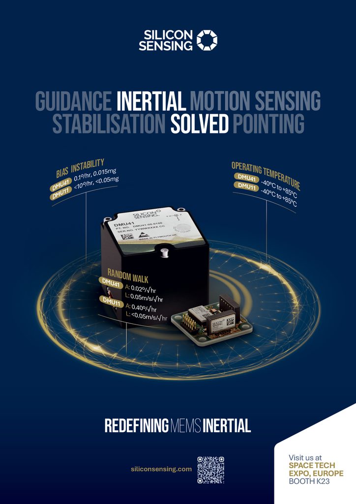
Often, the first cited is bias in-run stability – or instability, as it is also referred to, despite having the same definition and unit of measurement. This refers to the degree of random drift that the IMU’s readings (for both the gyroscope and accelerometer) exhibit over the course of a single run (typically balanced for external interferences such as temperature) after being powered on. That can, for instance, range from 0.9°/hr to 0.1°/hr for high-quality MEMS gyroscopes. Without decent bias stability, an IMU’s inherent errors will grow over time, especially in the absence of aiding sensors (like GNSS, star trackers or horizon sensors).
Angular random walk (ARW) typically follows swiftly in these discussions, and defines the gyroscope’s short-term attitude integration uncertainty; not dissimilar in practical terms to bias stability, a quality ARW will indicate a low degree of drift and a pleasing signal-to-noise ratio. For MEMS, ‘quality’ can mean ranging from 0.5°/√hr at the consumer end to 0.03°/√hr at the high end, while FOGs and RLGs can achieve 0.1–0.01°/√hr. ARW is also, notably, a crucial component for the effectiveness of many research and EO satellites, particularly with respect to fine sensor pointing performance and payload stabilisation.
Additional crucial metrics often considered for mission success include gyro scale factor error (or axis misalignment, depending on mission), which affects the angular rate error that can accumulate while a small satellite undertakes a somewhat agile manoeuvre, and bias repeatability, being the IMU’s anticipated variations in bias over its lifespan (accounting for power cycles). Additionally, bias versus temperature accounts for external factors and is vital for modelling how the IMU will actually perform in working conditions. Suppliers also increasingly endeavour to test, model and document how their IMUs perform over time with regards to changes in vibration, g-levels, radiation and other hazards typical of orbital or launch environments, which we explore further below.
While the precise nature of each mission will invariably determine the exact combination and prioritisation of IMU accuracy metrics, it is not a coincidence that all four of these most commonly prized specifications concern the gyroscope rather than the accelerometer. Most often, the IMU is leveraged for attitude determination and control systems, and parameters like bias stability and ARW from the gyroscope are key to minimising drift in attitude readings over time. Moreover, while the gyroscope will consistently track for orientation changes, accelerometers typically output measurements of zero, particularly while a satellite is orbiting Earth and in its own microgravity (although in rare cases, such as propulsive manoeuvres, and orbital position or gravity tracking, the accelerometer takes precedence as the more important of the two sensing devices).
MEMS IMUs
MEMS gyroscopes and accelerometers tend to come built around one of a variety of microscopic primary sensing items, varying from capacitive devices that measure changes in capacitance caused by inertial changes, to piezoresistive ones that exhibit changes in resistance in strain gauges in the core device, to piezoelectric devices emitting electrical outputs proportional to the degree of inertial change.
Popular MEMS gyroscopes especially tend to come in a particular range of designs, which function and perform in different ways. For instance, tuning-fork type gyro elements, typically made from silicon and utilising capacitive sensing, are widely-available and -used through being mass-manufactured and well-documented in a range of literature.
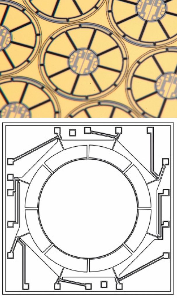
Growing in uptake are certain more proprietary designs, such as ring-shaped Coriolis vibratory gyroscopes (CVGs), which flex and vibrate in response to angular rate (through Coriolis forces), with that vibrational mode moving around the ring at an angle proportional to rotational velocity such that the resulting signal can be processed into measurable data. Moreover, the symmetry of the ring CVG shape is cited as key to their greater sensitivity, measurement precision, resolution and temperature stability (resulting in sub-0.1°/hr bias stabilities) compared with many other MEMS gyro technologies.
Another proprietary MEMS technology concerns a piezoelectric double-T or -hammerhead gyroscope made from quartz, which also vibrates owing to Coriolis forces during rotation, thereby generating signals that can be run through a differential amplifier, doubling the signal-to-noise ratio and enabling bias stabilities of 0.8°/hr as well as ARW of 0.03°/√hr. Beyond mere datasheet numbers, however, this approach also ensures consistent performance amid vibration (without incurring any extra power consumption or weight usage for it) because the mirrored movements of each T- or hammerhead-protrusion cancel each other out in the differential amplifier, enabling strong filtering-out of noise before digital filtering even begins.
Material differences often feed into IMU selections also. Silicon MEMS generally represent the smallest and lightest accelerometers and gyroscopes, not to mention the least costly per unit owing to the mass, semiconductor-like nature of their fabrication. While quartz devices are typically (but by no means always) larger and heavier, they generally exhibit superior accuracy and radiation tolerance, as well as strong temperature stability.
(Image: Silicon Sensing)
These advantages tend to grow even more pronounced when specifically comparing gyroscopes rather than accelerometers, which can make them more suitable for precision pointing applications, and in other operations at the higher altitudes of LEO and beyond where radiation levels mount. It is important to note, however, that while quartz can derive an inherent advantage over silicon owing to the former being a very pure, piezoelectric, crystalline dielectric substance, inherent material properties can be boosted or limited depending greatly on the overall MEMS design, and close scrutiny of the complete inertial system on a case-by-case basis can be hugely beneficial to the end integrator to avoid making sub-optimal selections based on material generalisations.
Fibre-optic gyros
The same can be said of comparing MEMS against FOGs. As mentioned, accelerometers are often less central to satellite mission success than gyroscopes, so it is not uncommon in LEO applications (and for farther-flung spacecraft where space-qualified IMUs are not deemed a requirement) to see IMUs pairing silicon accelerometers with quartz gyros and quartz accelerometers with FOGs.
Hence, a supply of single-axis accelerometers and gyroscopes, for either the supplier, integrator or both partnered together to then integrate selectively depending on differing cost and performance requirements, may often be preferable over fully integrated IMUs with their accelerometers and gyroscopes packaged inseparably. As well as picking and pairing different grades of inertial sensor together, it also allows systems integrators additional choices such as adding a fourth or fifth gyroscope for redundancy in one or more axes of rotation – with FOG customers often doing just that in their spacecraft.
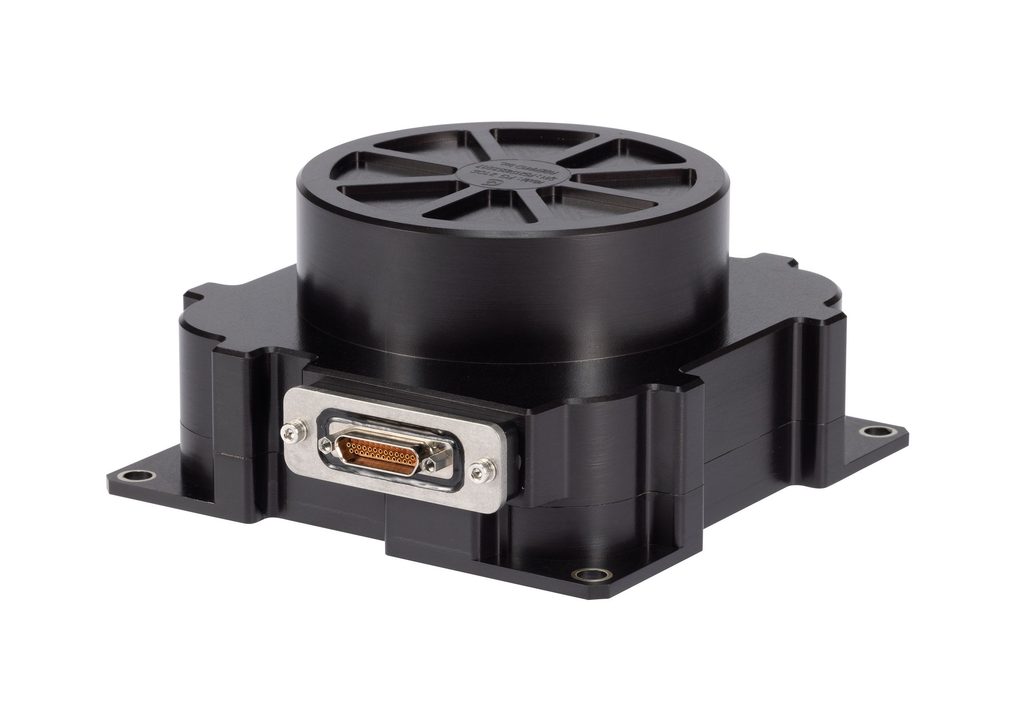
As a general rule, FOGs tend to exhibit more stable performance over environmental changes than MEMS, which can be vital depending on the mission. A great part of that comes from the differing means by which they measure angular rate: FOGs are interferometric devices, utilising the Sagnac effect by which a beam of light from a diode is split in two, those two beams then bouncing along the inside of a long, looped spool of optic fibre before returning to the light source at different times during rotation, and that differential then being processed to identify the angular rate with great accuracy.
The superior performance of the FOG is arguably most easily identified through comparing bias repeatabilities, which are one-to-three orders of magnitude lower in FOGs than MEMS gyros, with scale factor linearity or non-linearity being two-to-three orders of magnitude lower, making for generally far better bias and drift performance. However, FOGs must incorporate significantly more componentry – such as diodes and loops of fibre – making them more costly and difficult to manufacture with bulk automation than MEMS. The difficulty of tightly bending the fibre into small circles also limits by how much the size of a FOG can be reduced, although this has improved in recent years.
While these SWaP-C disadvantages can make FOGs a challenging choice for some LEO applications, their precision and accuracy can be ideal for longer missions and pointing applications. But before selecting them for higher-altitude LEO or GEO missions, it is important to identify whether the FOG manufacturer has taken the minimum radiation countermeasures. Crucially, radiation-induced attenuation is a significant concern affecting optical transmissions in certain specific fibre types; as radiolytic electrons and holes become trapped in the fibre, they form light-absorbing colour centres, which then weaken the optical signal and increase both random walk and scale factor error.
The degree of radiation-induced attenuation is closely linked to the fibre type and amounts of certain dopant used; fibres with germanium- and phosphorus-doped cores, for instance, are the most severely affected by radiation. Hence, minimising the quantities of materials such as these and opting for radiation-tolerant fibres as well as good radiation hardening can be vital for ensuring that a FOG is spaceworthy.
As platforms ascend from GEO to MEO, and bring with them more critical missions and larger budgets, the tendency will be towards high-end FOGs as well as RLGs and HRGs, including with redundancies. RLGs and HRGs in particular are highly capable of maintaining accuracy for long periods without star or sun sensor inputs, although their significant unit prices make them overkill for many applications; RLGs must also exhibit strong sealing performance to prevent depletion of their internal gases, and HRGs can be challenging to scale production up to significant numbers – disadvantages that FOGs do not bear.
Testing
(Image: FIBERPRO)
High-end suppliers of IMUs, whether MEMS, FOG or other types, often go to great lengths to perform in-house calibration and compensation for several key parameters, testing methodologies for these engineering processes often being informed by standards set by groups like the IEEE Aerospace and Electronic Systems Society’s Gyro and Accelerometer Panel. Following their guidelines – which define different standards for many different IMU technologies, including tuning-fork, Coriolis vibratory and fibre-optic gyros – can ensure good working order in new designs before they are approved for production, and also establish compensation parameters at the level of individual manufactured units to support stable performance across finished output batches.
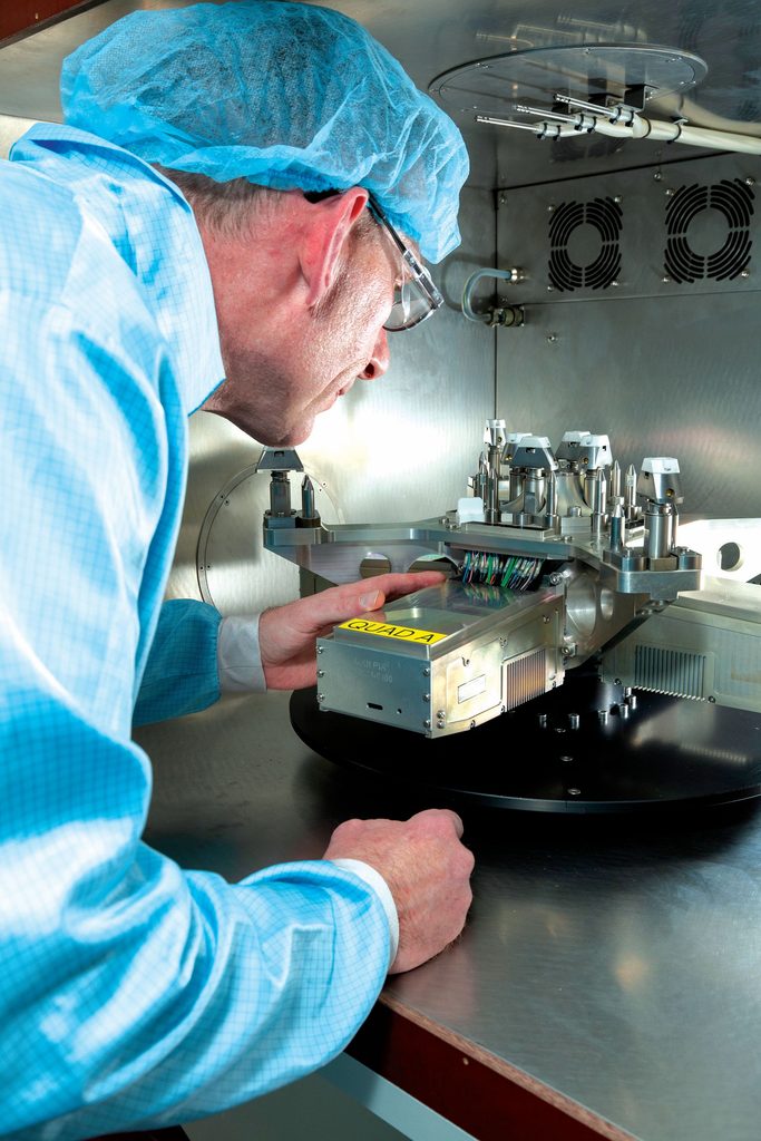
For example, calibrating for sensor alignment often comes down to using quality, temperature controlled, dual-axis rate tables by which all three gyro axes can be calibrated in a single set-up, although three-axis rate tables can help characterise g-sensitivity.
In fact, rate tables running in a temperature- and climate-controlled chamber (typically running in the -40 to +85 °C temperature range standard for IMUs) can also successfully extract other key parameters that need calibrating for, including scale factors and biases, although bias can also be more easily measured through static runs, still temperature-controlled but on a perfectly stationary testbench for many hours.
For the most part, engineering IMUs tends to follow similar processes whether designing solutions for space or in-atmosphere – with the critical exception of engineering for tolerance of key environmental hazards unique to space. As well as radiation, as already touched upon to a degree, this will also often include some measure of sealing against factors specified by the end user.
Thermal vacuum tests can be a strong indicator of a system’s ability to maintain normal operations under very close simulation of space environments because these involve running devices in powerfully vacuumed chambers under severe temperature cycling, recreating the LEO flight patterns of satellites rapidly moving between Earth’s cold side, shielded from the sun, and the hot side with prolonged direct exposure to solar radiation.
Arguably more nuanced test programs may investigate hermetic sealing of the IMU, as well as its ability to tolerate the kinds of helium (He) exposure that can occur during launches. Claims of the former may not necessarily guarantee the latter because hermeticity is defined by a measured leak rate, not by being leak-proof – and He is the geometrically smallest atom in existence, making it very possible for He to leak into hermetically sealed components.
MEMS devices in particular can suffer increased drift or certain malfunctions when He ingresses through their enclosures, and the higher the concentration of He gas around them, the quicker and likelier this may happen either during or shortly after launch. It can, however, be challenging to identify whether an IMU will be capable of tolerating such exposure for relevant lengths of time; high protection ratings such as IP67 or usage of quality ceramics and other housing materials can be a good clue that the manufacturer has done their due diligence with regards to sealing quality, if not providing a wholly practical guarantee of He tolerance.
Thus, He exposure resistance testing is increasingly requested for IMUs intended for satellite applications, and such tests invariably consist of pumping high-purity He gas into a controlled chamber where one or more IMUs can be monitored for several hours to track and compare performance degradation. As a baseline, MEMS utilising piezoelectric measurements have exhibited more prolonged stability amid He exposure than capacitive MEMS, although again, various protective approaches may be tried that bear trial and evaluation on a case-by-case basis.
The same goes for radiation testing: many datasheets on IMUs supplied for spacecraft integration will, for instance, list such stats as ‘10 kRad TID [total ionising dose]’ to indicate that such radiation testing was performed to the benchmark typically associated with LEO operations, with some companies increasingly going beyond 20 kRad TID to prove applicability for higher LEO and lower GEO altitudes (particularly if equipped with additional shielding), but it is important to look deeper for context as to how the IMU actually performs in response to radiation events.
As a start, it can be useful to investigate whether Single Event Effects tests were also performed on a given IMU, these gauging response to occasional high-energy strikes including instant disruptions to operations, unlike TIDs which are meant to track cumulative degradation over the lifetime of a mission.
Moreover, given that some incidence of radiation events is almost bound to affect a satellite at some point, and that an IMU may well serve primarily as a temporary bridge or gap-filler between updates from star trackers, sun sensors or GNSS signals, certain levels or durations of losses in inertial data accuracy or output rate may be tolerable, so long as (importantly) the nominal performance levels are recoverable afterwards, for instance through a power cycle.
At least one silicon IMU supplier manages this through a reset architecture, based around a watchdog that monitors the IMU’s main processor, and internally resets the device after detecting a lockup (this being the likeliest outcome of a high-energy radioactive strike), meaning that the IMU can always recover its normal operating capacity without lasting performance degradation, even when a full power cycle is necessary to clear the effects of a radiation event.
Manufacturing
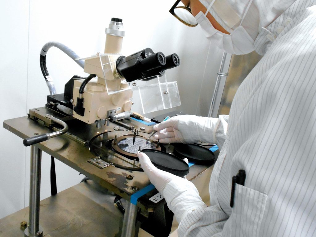
As indicated, the production of MEMS closely resembles the production of most semiconductor devices, which contributes greatly to the former’s capacity for volume and prices on par with the latter. Quality in MEMS IMUs, therefore, often comes down to ensuring robust design and QC practices, such that the highly automated production processes for vacuum or hermetic sealing, photolithography or etching of sensors down to the level of material wafers, and pick-and-placing of components onto circuit boards can achieve quality arrangements of quality input components.
(Image: Silicon Sensing)
To illustrate, in most cases, the MEMS sensing element will be packaged in some way into some form of application-specific integrated circuit or equivalent, which then must be soldered or similarly bonded onto a PCB. As much as primacy should be given to the sensing element when it comes to judging product accuracy and reliability, the quality of that solder and that PCB will have significant impact on the performance of the IMU.
If, for instance, the chosen PCB flexes under vibration or warps under high thermal loading, the IMU’s performance will be altered considerably from nominal parameters. Such alteration may also occur depending on the temperature profiles used during soldering to mount the accelerometers and gyros into the IMU. While the calibration processes during both engineering and manufacturing can compensate for much, they cannot necessarily compensate for mechanical defects such as these, hence extensive QC checks on not only finished units but incoming subcomponents for stock can save the customer and satellite operator immense trouble down the line.
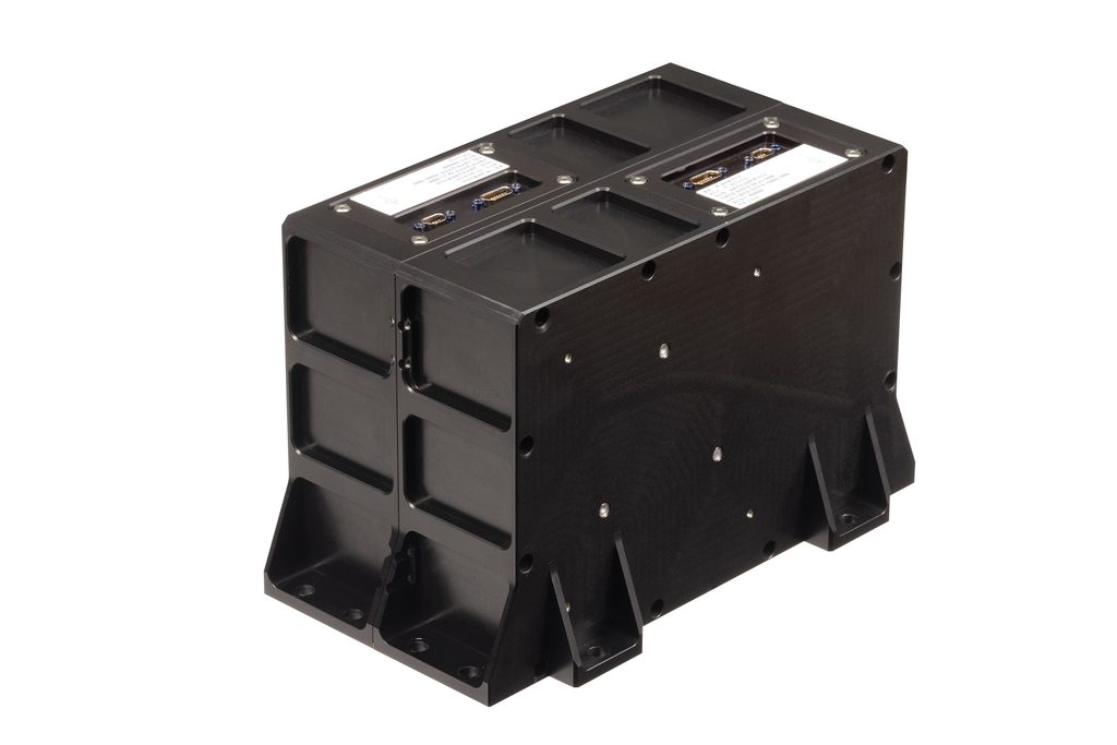
FOGs, meanwhile, are manufactured by first extruding (typically just by gravity) the optical fibre to the exact thinness and length required, that length going hand-in-hand with the accuracy of the gyro. After that, the fibre is wound into a coil to suit the end product’s size and packaging, with the coil subsequently being coupled with the diode (or other light source), the splitter and a signal detector before those components get integrated into an enclosure.
Naturally, changes to a FOG product’s design can entail extensive alterations to existing machinery and tooling, or acquisitions of new production systems entirely, to make certain that the optic fibre can be configured, welded, coated and so on as needed. As a result, it can take five or more years of R&D for new generations of FOG to come out. However, many leading FOG suppliers are reconfiguring and expanding their manufacturing facilities to enhance their productive capacity several times over, which can be expected to enable not only faster iterations of FOG products but also considerably higher volumes and reduced unit costs. Thus, just as MEMS devices encroach upon the performance heights of FOGs, so too do FOGs slowly creep in the direction of the kinds of prices and batch sizes typically boasted by MEMS.
Future
Going forwards, IMU designers will endeavour to continue chasing improvements in both short- and long-term performance for their devices, particularly with an eye towards maintaining consistently minimal drift over lifespans and amid radiation and thermal events, and figuring out how to do so without needing to use larger, heavier, more powerful accelerometers, gyroscopes or processors.
For FOGs and larger systems, this may mean creative new ways of integrating thermal management solutions and materials to inch closer towards truly stable bias over temperature. Among MEMS, one may see a few standout suppliers developing new means towards navigation-grade performance in very small packaging, be it through intelligent error modelling algorithms, data fusion, machine learning or a combination of these and other approaches.
(Image: FIBERPRO)
Regardless of the methods or technologies, IMU manufacturers seem invariably determined to keep chasing the dream of zero drift, and their efforts will be vital for enabling spacecraft to navigate ever farther, with precision, safety and reliability.
Acknowledgements
The author would like to thank Ed Smith at Silicon Sensing, Francesco Sabella at Epson Europe Electronics, and Bong-Wan Lee, Richard Ryu and Justin Hong of FIBERPRO, Inc for their help in researching this article.
Some suppliers of IMUs
FRANCE
| Exail | +33 130 088 888 | www.exail.com |
GERMANY
| Epson Europe Electronics | +49 89 14005 0 | www.epson-electronics.de |
NORWAY
| Safran – Navigation & Timing | +47 3303 5000 | www.safran-navigation-timing.com |
SOUTH KOREA
| FIBERPRO | +82 42 360 0030 | www.fiberpro.com |
UK
| Silicon Sensing | +44 1752 723 330 | www.siliconsensing.com |
| SMG Motion | +44 1223 608 830 | www.smgmems.com |
USA
| Analog Devices | +1 978 250 3343 | www.analog.com |
| EMCORE | +1 626 293 3602 | www.emcore.com |
| Gladiator Technologies | +1 425 396 0829 | www.gladiatortechnologies.com |
| Honeywell Aerospace | +1 602 365 3099 | www.honeywellaerospace.com |
| Kearfott | +1 973 785 6000 | www.kearfott.com |
| Silicon Designs Inc | +1 425 391 8329 | www.silicondesigns.com |
UPCOMING EVENTS