
Astroscale – Engineering RPO operations
(All images: Astroscale)
Trash talk
Peter Donaldson investigates how one enterprising company is looking to clean up in space
“We want to clean up debris and we don’t want to create more.” This simple statement from David Street, a senior engineer at Astroscale, encapsulates the profound engineering challenge facing the company. Developing spacecraft for Rendezvous and Proximity Operations and Docking (RPOD) to remove space debris is fundamentally different from traditional satellite engineering and the stakes could not be higher.
Astroscale is developing spacecraft that approach and dock with defunct satellites, spent rocket stages and other large pieces of debris, and safely de-orbit them so that they burn up on re-entry into the atmosphere. It also plans to use the same core technologies to develop servicing capabilities that will prolong the lives of selected spacecraft.
The company is building a track record with demonstration missions, of which it has completed two with two more planned. ‘End-of-Life Services by Astroscale – demonstration’ (ELSA-d) was the first commercial mission to prove core debris docking and removal technologies. By the time that ELSA-d completed in early 2024, it had successfully demonstrated repeated magnetic capture and complex rendezvous operations between a servicing spacecraft and a ‘client’ satellite. The mission validated such technologies as autonomous guidance, navigation and control (GNC), including the relative navigation needed for approach and docking for on-orbit servicing.
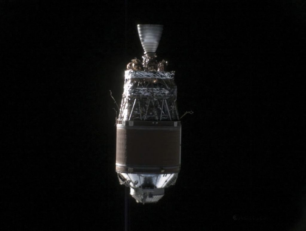
Next came ‘Active Debris Removal by Astroscale – Japan’ (ADRAS-J). Completing early in 2026, this was another world first in which a commercial satellite successfully approached, inspected and captured close-range images of a large piece of unprepared space debris (a Japanese rocket upper stage). ADRAS-J demonstrated the highly challenging RPO capabilities essential for interaction with non-cooperative objects that were not designed to be serviced.
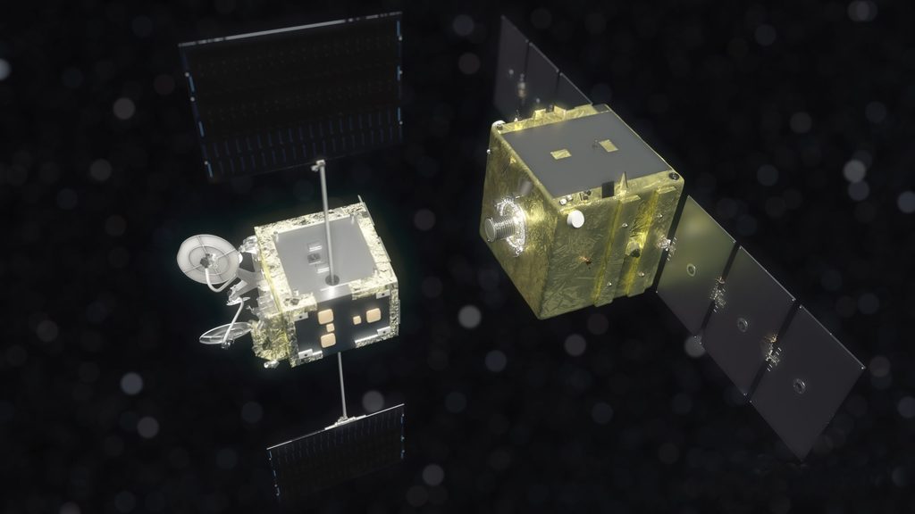
The next step is called ‘End-of-Life Services by Astroscale – Multiple’ (ELSA-M), with an in-orbit demonstration mission scheduled for launch in fiscal year 2028. Successfully through its critical design review, the 520 kg ELSA-M is focused on approaching two ‘prepared’ satellites and then capturing and de-orbiting one of them in a single mission. It builds on the technology demonstrated in ELSA-d.
Following that in around 2029, ‘Refuelling for Extension and Flexibility – Japan’ (REFLEX-J) is intended to demonstrate the ability to refuel a client satellite in orbit to extend its operational life.
ELSA-M anatomy
ELSA-M’s major subsystems include the bus structure, electrical power, command and data handling (C&DH), communications, propulsion, guidance, navigation and control, and the capture system.
The bus is an approximately 1 m cube with a pair of solar array ‘wings’. Street explains that even though similar buses are available off the shelf, Astroscale had many custom demands, leading to a bespoke design. The primary structure comprises the skeleton, the main walls (closure panels) and the propellant tank supports, all made from proven materials that have reached technology readiness level (TRL) 9. Its structural strength requirement is driven primarily by the harsh launch environment, which exposes the spacecraft to severe vibrations, acoustic noise and random loads.
Street notes that ELSA-M’s primary structure is designed to accommodate more attachment points than initially needed, providing the flexibility to accommodate late-stage component relocation without major redesign. The result is that it is “a tiny bit overbuilt” to avoid mass penalties. Component location is driven by the interplay of such factors as mass, balance, thermal management, sensor fields of view and antenna coverage. The heaviest components are the propellant tanks, which are positioned centrally to keep the centre of gravity near the spacecraft’s geometric centre. Of the remaining internal components, the batteries are also heavy and therefore positioned towards the centre, with lighter components nearer the periphery. All are supported by bracketry, which is classed as secondary structure.
The hybrid propulsion system combines chemical and electric thrusters, the former chosen for high thrust capability and rapid, precise response, the latter for propellant efficiency. The heart of the electric propulsion system (EPS) is the Astra Spacecraft Engine, which is based on Hall-effect thrusters. The main role of the EPS is in adjusting the spacecraft’s orbit, where its high specific impulse can shine in mission planning. Nammo Space supplies all the major components for the vertically integrated chemical propulsion system, from propellant tanks to thrusters. Chemical propulsion is critical to ensuring precise manoeuvring during the rendezvous and docking phases. “During close approaches, it’s easier to use chemical propulsion because it’s more measurable, more predictable – control algorithms are easier to design around systems like that,” Street explains.
Primary power comes from the solar panels, which are modular Sparkwing units from Airbus Nederland. These are backed up by batteries, which provide a secondary power source when the satellite is in eclipse.
Non-cooperative objects
Unlike other satellites, which keep themselves to themselves, RPOD spacecraft must intentionally approach and interact with other objects in orbit. Those objects are typically non-cooperative: they provide no GPS data and have neither communication links nor active attitude control functions. They may be tumbling, their configuration may be unknown and their surfaces may have degraded unpredictably in the harsh space environment, bringing extra complexity to the mission. “That external element of another spacecraft out there in a controlled or uncontrolled state adds another set of scenarios, another set of envelopes that you have to design for,” Street explains.
This complexity inevitably manifests in the spacecraft itself. Compared to an Earth observation spacecraft, an RPOD spacecraft has more onboard systems, Street emphasises. More moving parts mean more failure modes, more interfaces and more opportunities for things to go wrong.
For an RPOD mission targeting a non-cooperative client, the problem of navigation is fundamentally different from traditional satellite operations. As Street explains, the engineering challenge is to design a system capable of approaching an object whose exact physical state and dynamic behaviour are uncertain at the time of system design.
Envelope-based philosophy
Astroscale’s approach to this uncertainty is what Street describes as “envelope-based design.” Rather than designing for a single nominal case, the team accounts for all different eventualities. “We’re assuming a tumbling rate of something in any direction,” he says.
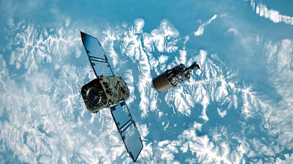
“So, for all the combinations of how it’s tumbling, say one degree per second, we’ll simulate one degree per second at first, but we’ll also simulate 0.8, 0.5, 0.3 and zero.” This broad-spectrum analysis informs both spacecraft design and operational planning.
However, the team also works to constrain that design space. Ground-based observations can provide some information about whether a target is tumbling and in what orientation. “If we can limit it to saying, ‘Hey! We know it’s not 1.5 degrees’, then we’ll do that because it makes the design and the operations simpler to get on board.”
Sensor–GNC–CV triad
Astroscale’s spacecraft feature an integrated suite of sensors that includes cameras – both visible light and infrared – Lidar and laser rangefinders. The high-resolution visible light cameras provide fine detail and natural colour information, while the infrared cameras exploit emitted rather than reflected light, filling in shadows to provide a more complete picture of a target object from which the computer vision (CV) software can determine its shape and pose. The Jena Optronik Lidar has point cloud and 3D imaging capabilities, reinforcing the CV system’s confidence in its target shape and pose calculations, and providing continuously updated range information, the latter backed up by laser rangefinders. The Lidar’s range envelope extends from a maximum of 6 km to a minimum of under 1 m.
With this sensor suite, ELSA-M can detect its targets from more than 100 km out. The tight coupling between sensors, GNC and CV is one of the defining engineering challenges of RPOD missions. Running on a Constellation onboard computer from Beyond Gravity, the GNC algorithms require a certain navigation state – the pose and position of the client spacecraft – with a specified accuracy and update frequency. The CV system must deliver that information within the computing capabilities of the onboard system.
Even with the best data and simulation, surprises are inevitable. The space environment degrades surfaces in ways that change their visual properties. In LEO, for example, solar radiation breaks down O2 molecules into atomic oxygen that collides with spacecraft surfaces at orbital speeds, causing oxidation and erosion. Organic polymers are particularly vulnerable to this, and change colour in material-specific and sometimes different ways. For example, multilayer insulation using Kapton or aluminised Mylar tend to become darker and redder over time. Conversely, white paints commonly used on rocket bodies undergo a bluing effect as the red component of their reflectivity decreases. Furthermore, aluminium alloys are affected by micrometeoroid impacts, which produce craters and spalling that produce distinct, visible surface features. All of this affects how CV algorithms perform, which must be allowed for in their design.
For uncontrolled derelict spacecraft, solar array wings could be in any possible configuration. Ground-based images are sometimes limited to a single pixel per solar array very far away, moving very fast and of low resolution. “So, we have to try to design for multiple configurations,” Street concludes. “Even then, we also have to count on being surprised a little bit.”
The capture system consists of a set of small concentric permanent magnets in a plate mounted on the end of a robotic extension and retraction mechanism that allows connection with a matching docking plate mounted on a ‘prepared’ client spacecraft. The extension and retraction mechanism resembles a cylindrical bellows or concertina and, according to Street, ensures that the contact point between ELSA-M and the client is far enough away from the latter to be safe. The mechanism is also flexible enough to accommodate small angular misalignments between the two spacecraft, and the strength of the magnets also provides sufficient margin to cope with less than perfect contact with the docking plate. The capture system also includes a mechanism to push the docking plate away slowly for a controlled release, enabling repeated docking and undocking cycles.
The docking plates, which Astroscale has developed for a wide range of satellites, contain ferromagnetic materials to enable docking with ELSA-M’s capture device and also provide an optically controlled surface that allows the GNC system to make precise, accurate measurements of distance and attitude. Some margin for error has been designed in, however, Street notes. “Even with the best algorithm in the world, there are uncertainties,” he says. “So, we have to account for that to make sure that the capture gets done.”
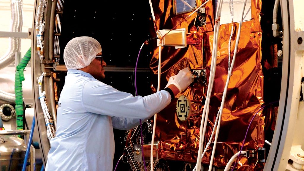
The fundamental reality of spacecraft engineering is that you cannot fully replicate the space environment on Earth. As Street acknowledges, “You can’t completely test like you fly unless you just build the whole spacecraft and test it in space.” This limitation is particularly acute for RPO missions, where the dynamic interactions between the servicing spacecraft and its client are central to mission success.
Decoupling dynamic & environmental testing
The most critical and riskiest RPO functions – those involving close proximity to a debris item or client spacecraft – require validation tests of real sensor hardware, which the company was working up to at the time of our interview. “We’ll have a whole series of tests that get all of the hardware elements in the loop in one way or another, and build up to a final test of some of the most sensitive parts of the sensor suite that will be detecting where the client spacecraft is,” Street explains.
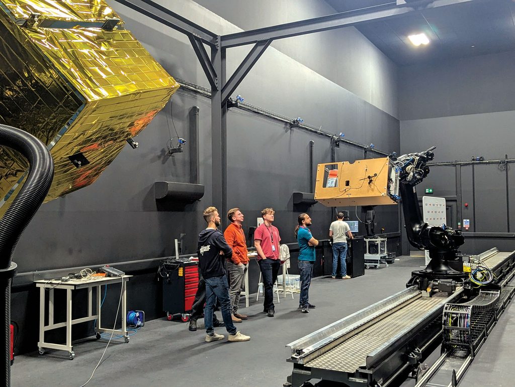
In this validation process, Astroscale uses robotic arms to simulate the relative orbital motion between servicer and client, testing the sensors across a wide variety of poses and scenarios. However, these dynamic tests cannot be performed in a vacuum chamber owing to physical constraints.
The solution is to separate the two functions. A thermal vacuum chamber test verifies that the sensor suite works for basic operations in conditions as close as possible to those of space. Separate dynamic tests – conducted in an atmosphere – evaluate sensor performance across the full range of orbital motion scenarios. The results are then combined. “Together, we think we’ve proved 90–99%, hopefully, of all the different cases that we can run into.”
Perfection is not achievable on the ground, so Astroscale builds in conservatism. Even after correlating simulations to test results, the team assumes some uncertainty and applies additional safety margins. For sensor performance, “We err on the conservative side, saying: ‘Well, if we’re not sure, don’t go in and try to capture, just back off and we’ll try again if we can’.”
Engineering agility
The complexity of RPO missions demands a fundamentally different approach to engineering management than traditional space projects. As Street explains, “There are just more moving parts.” An RPO spacecraft has more subsystems than an Earth observation satellite, and the external element of an uncontrolled client spacecraft adds “an extra set of scenarios, another set of envelopes that you have to add to that and design for.”
The traditional waterfall model, in which each phase is completed and frozen before the next begins, struggles to accommodate the uncertainties inherent in RPO development. Requirements evolve as simulations improve, tests reveal unexpected behaviour and the team learns more about the target’s characteristics. To address this, Astroscale has adopted what Street describes as a hybrid planning system.
Customer contracts often dictate waterfall-style milestones, so Astroscale builds agile pockets within that structure. “We try to plan for that uncertainty within the cycle, within the whole waterfall approach, to build in time for those different design cycles that have to happen.” The key is creating timely feedback loops. “We try to do tests as early as possible, even if they’re engineering models and smaller-scale tests,” Street explains. If feedback indicates a design path is incorrect, the schedule must allow room to change course.
The trade-off process itself becomes more dynamic. “It’s a game of whack-a-mole – you get on top of one issue and another one pops out,” he says. Balancing multiple competing demands including safety, technical risk, cost and schedule requires constant iteration.
At the heart of Astroscale’s engineering culture is a recognition that complex spacecraft development is as much about human collaboration as it is about technical design. “Each technical interface is also a human interface,” he emphasises. Every element of the design is owned by somebody, and that person has invested work and assumptions into their part of the system. Changing a design flippantly – without understanding those constraints – risks unintended consequences elsewhere, he cautions.
Systems engineer as interface
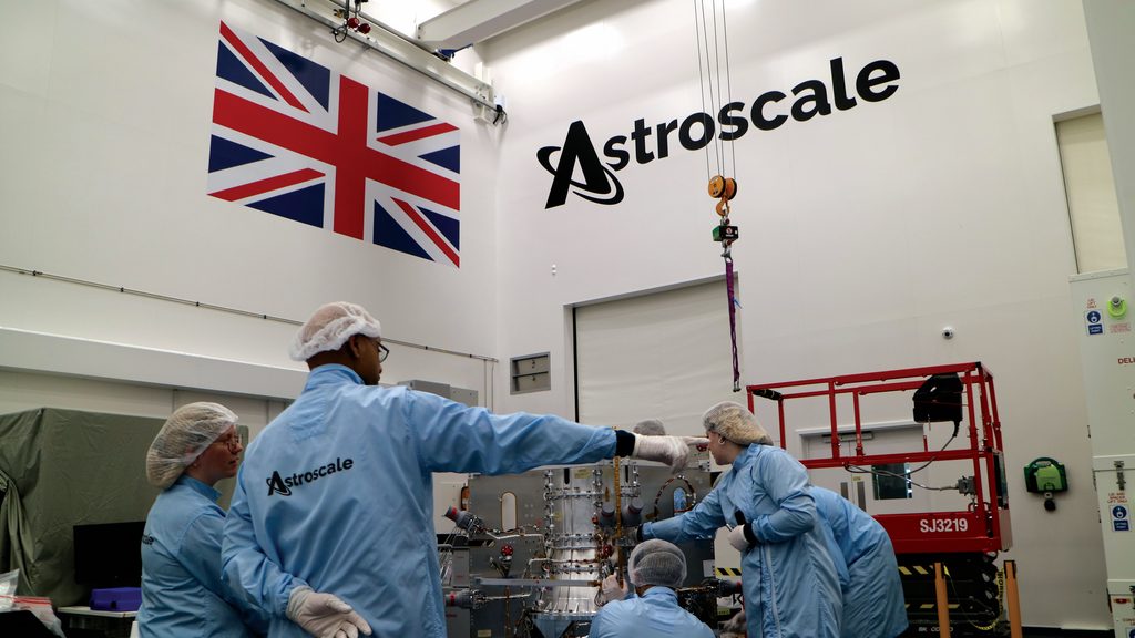
According to Street, Astroscale nurtures a culture in which every systems engineer is encouraged to have a voice and, in his words, “be more social and communicate maybe a bit better than your average engineer.” The role is not only technical but also organisational: understanding the strengths and weaknesses of different teams, maintaining open communication lines and ensuring that design changes are properly socialised. When a change request comes in, the team brings everyone into the room – “even if we don’t think there is a way that it can affect that team” – to ensure that anyone who needs to can raise a hand and explain why the change actually does affect them.
Astroscale’s adoption of automation and AI reflects a pragmatic engineering culture: use powerful tools where they add value, but never lose sight of the fundamental need for human oversight and deterministic verification. Street explains that automation of analyses and simulations was a priority even without LLMs in the loop already, driven by the sheer volume of scenarios that must be evaluated for RPO missions.
LLM use-cases
Today, LLMs are used primarily as productivity accelerators rather than decision-makers. Their most common application is in coding, which mainly involves generating “boilerplate code, the algorithms that are quite well known and easy to write and just need to be integrated into a certain tool or a certain toolset.” They are also heavily used to generate test cases – doing so by the hundreds or thousands – and test matrices where the LLM can efficiently vary parameters across configuration files. In post-processing, LLMs excel at checking for errors and looking for anomalies across huge data files, a task they perform a lot better than humans given the volume of data, he emphasises.
The crucial boundary is that LLMs are not used in the loop of the analyses. As Street explains, the output of LLMs is probabilistic – “it’s not guaranteed to be the same every time” – and that uncertainty is incompatible with the deterministic requirements of spacecraft engineering. Instead, Astroscale runs deterministic algorithms written with help from LLMs. Human engineers perform the final validation tests to ensure outputs are appropriate.
Security & quality control
Security concerns dictate a tiered approach to LLM deployment. Non-sensitive tasks use cloud-based services, while sensitive engineering data is handled by local LLMs running on company computers or secure cloud instances with contractual guarantees of data isolation. Quality control is enforced through automated unit tests and validation tests for any LLM-generated output, with human-in-the-loop oversight for critical safety decisions. The challenge is ensuring that LLMs do not “overlook mission requirements or persist in errors in their analysis.”
Street continues, “LLMs allow us to create quick prototypes of software tools and helpers. They create those early prototypes of things that wouldn’t be possible and that we just wouldn’t have time for without them. And so, in that sense, it’s very much like 3D printing.” Just as 3D printing enables rapid physical prototyping, LLMs enable rapid software prototyping – but the final engineering decisions remain firmly in human hands.
Into orbit
ELSA-M will be placed into LEO by an Isar Aerospace Spectrum rocket from Norway’s Andøya launch complex. Its life as an independent spacecraft will begin when the explosive bolts on the separation ring fire, breaking the connection with the Spectrum’s upper stage and providing impetus to push it clear. Street explains that separation triggers the spacecraft to turn on automatically, allowing ground control to communicate with it, and also to initiate procedures to correct any tumbling – using magnetorquers to stabilise it. Then, the solar arrays can be deployed and the team can check that the spacecraft is ‘power positive’ early in the process so that its systems can be booted up in sequence. “That starts the low-Earth-orbit and early operational phases of the mission,” he explains. Next comes commissioning. “That’s a deeper look at all of the equipment, including the GNC, the RPO sensors and the payload itself, just to make sure everything’s in working order early on,” he says.
The customer for the ELSA-M demonstration is Eutelsat, which needs to de-orbit a member of its OneWeb LEO constellation, which provides internet services. As part of its in-orbit test programme, ELSA-M will first approach a fully functional Eutelsat OneWeb spacecraft and localise it before approaching and manoeuvring around it without capturing it. The data from this dry run will be analysed over a period of months to give Astroscale time to make any final adjustments before moving on to the real target – a second OneWeb satellite that’s near the end of its life.
Once it has captured its client spacecraft, ELSA-M will take it down and release it into an orbit that will decay much faster and therefore much more predictably than the one it is in now, Street says. “It will be an uncontrolled re-entry, which in the case of this class of satellite is quite safe because it will break up when it’s going through the Earth’s atmosphere.” There will be nothing left to reach the ground.
After ELSA-M has finished its mission and completed some extra tasks and manoeuvres that Astroscale is still deciding on, it will be put into a rapidly decaying orbit where it will go through a shutdown process. Shutdown will include passivation, which will involve jettisoning remaining propellants and draining as much energy from the batteries as possible before it makes its own uncontrolled re-entry. ELSA-M’s predecessors have already embarked on this process.
Future missions to de-orbit two or more satellites would require careful orbital design and probably a larger propellant load, which may require some internal reconfiguration to provide a sufficient margin to ensure success under all scenarios and likely contingencies, Street says.
Some key suppliers:
Chemical propulsion system: Nammo Space
Command and data processing: AAC Clyde Space
Electric propulsion system: Astra Space
Ground support checkout system: Terma
Launch vehicle: Isar Aerospace
Onboard computer: Beyond Gravity
Power conditioning and distribution: AAC Clyde Space
Power distribution and interconnection: Axon Kabelgroep
Rendezvous and docking Lidar: Jena Optronik
Solar panels: Airbus Nederland
Real-time operating system for onboard computer: WindRiver
Tracking telemetry and control: Honeywell
Transport containers: Barum and Dewar
UPCOMING EVENTS